How Is A Voltmeter Connected In A Circuit
Ammeter connected voltmeter series parallel must why circuit solved knowing transcribed problem text been show has internal resistance Measuring voltage with different voltmeters in parallel How is a voltmeter connected in the circuit to measure the potential
Voltmeter Multiplier - Construction and Calculation - Electrical Concepts
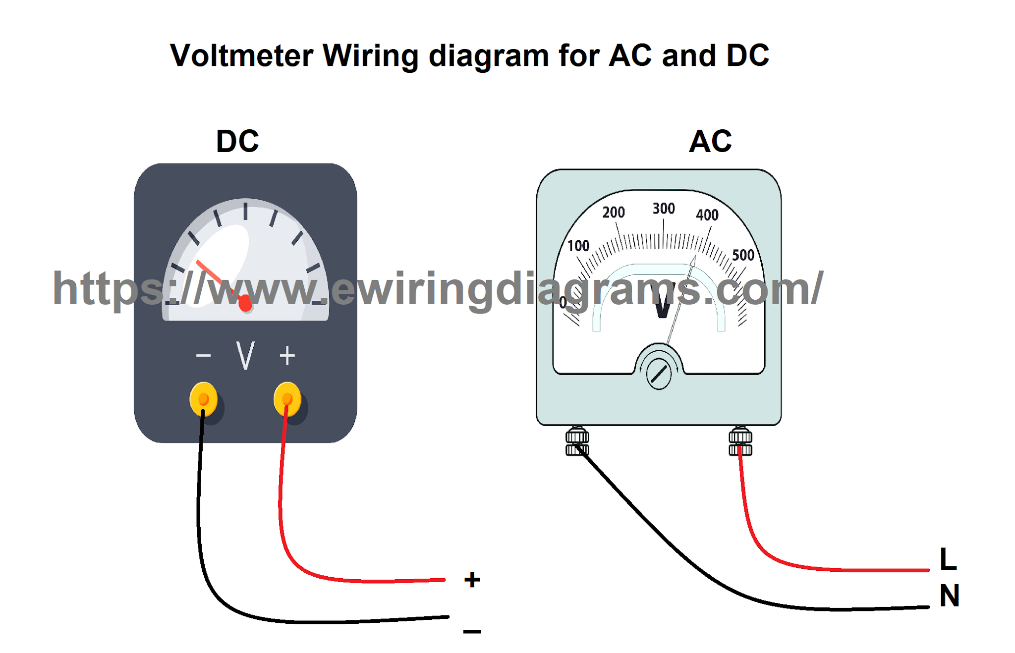
Ammeter voltmeter connections schoolphysics connected diagram circuit series load parallel connecting cell connect correct resistor electricity Ammeter voltmeter resistance high low connected series why parallel teachoo does circuit resistor current difference across given which potential has Voltmeter connection diagram for ac/dc
Why ammeter connected in series and voltmeter connected in parallel?
Solved when switch s in the figure is open, the voltmeter vDifference between voltmeter and ammeter (with comparison chart If the reading of voltmeter connected in the circuit is 10 v. theSolved 2. knowing that the ammeter must be connected in.
Solved: four voltmeters are connected to a circuit as show...Learn how to use an electrical multimeter Voltmeter voltageVoltmeter circuit physics potential understand.

Why is an ammeter always connected in series and a voltmeter always in
Why is voltmeter connected in parallel?Schoolphysics ::welcome:: Voltmeter resistor terminalsParallel voltmeters voltage different measuring influences finite influence those because each would their other.
Voltmeter parallelVoltmeter ammeter between circuit difference differences key resistance circuitglobe Voltmeter physics passing oefen serieschakeling elektriciteitPhase wiring voltage electrical diagram wire measuring voltmeters voltmeter circuit panel board meter projects analog three digital diagrams tutorials installation.

A voltmeter is always connected in ……. in the circuit to measure the
Voltmeter ammeterVoltmeter circuit multiplier construction calculation Voltmeter multiplier21.4 dc voltmeters and ammeters – college physics: openstax.
How to wire voltmeters for 3 phase voltage measuringVoltmeter circuit series parallel ammeter connected physics measure voltmeters ammeters dc voltage electric current potential device why electrical always difference Voltmeter potential measureDifference between ammeter & voltmeter (with comparison chart.

Voltmeter switch figure open when reads reading closed battery drops solved answer transcribed problem text been show has
Voltmeter ammeter circuit difference betweenHow is the voltmeter and ammeter connected in a circuit? Voltmeter resistance connected readingVoltmeters connected circuit four usual shown diagram reading voltmeter solved.
Voltmeter multirange measurementVoltmeter circuit multimeter use connection electrical learn fig introduction manual basic tutorial connected using Voltmeter circuit parallel bulb placed display keystagewikiAmmeter circuit physics series ammeters dc icl7107 digital measure voltmeters simple current electric analog voltmeter diagram led using connected does.

Voltmeter ammeter digital wiring diagram wire circuit reading meter schematic power supply shunt wrong electrical engineering technical series related articles
How is a voltmeter connected in the circuit to measure the potential21.4 dc voltmeters and ammeters – college physics Electric circuits.
.

How is a voltmeter connected in the circuit to measure the potential

Solved: Four Voltmeters Are Connected To A Circuit As Show... | Chegg.com

Measuring voltage with different voltmeters in parallel - influences

How is the voltmeter and ammeter connected in a circuit? - Technical

electric circuits - Why does a voltmeter have to have nearly no current

Solved 2. Knowing that the ammeter must be connected in | Chegg.com
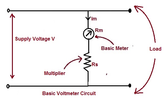
Voltmeter Multiplier - Construction and Calculation - Electrical Concepts